Search This Blog

Wednesday, July 19, 2017

Chemical polarity

From Wikipedia, the free encyclopedia
A water molecule, a commonly used example of polarity. Two charges are present with a negative charge in the middle (red shade), and a positive charge at the ends (blue shade).

In chemistry, polarity is a separation of electric charge leading to a molecule or its chemical groups having an electric dipole or multipole moment.

Polar molecules must contain polar bonds due to a difference in electronegativity between the bonded atoms. A polar molecule with two or more polar bonds must have an asymmetric geometry so that the bond dipoles do not cancel each other.

Polar molecules interact through dipole–dipole intermolecular forces and hydrogen bonds. Polarity underlies a number of physical properties including surface tension, solubility, and melting and boiling points.

Polarity of bonds

In a molecule of hydrogen fluoride (HF), the more electronegative atom (fluoride) is shown in yellow. Because the electrons spend more time by the fluorine atom in the H−F bond, the red represents partially negatively charged regions, while blue represents partially positively charged regions.

Not all atoms attract electrons with the same force. The amount of "pull" an atom exerts on its electrons is called its electronegativity. Atoms with high electronegativities – such as fluorine, oxygen and nitrogen – exert a greater pull on electrons than atoms with lower electronegativities. In a bond, this leads to unequal sharing of electrons between the atoms, as electrons will be drawn closer to the atom with the higher electronegativity.

Because electrons have a negative charge, the unequal sharing of electrons within a bond leads to the formation of an electric dipole: a separation of positive and negative electric charge. Because the amount of charge separated in such dipoles is usually smaller than a fundamental charge, they are called partial charges, denoted as δ+ (delta plus) and δ− (delta minus). These symbols were introduced by Christopher Kelk Ingold and Edith Hilda Ingold in 1926.[1][2] The bond dipole moment is calculated by multiplying the amount of charge separated and the distance between the charges.

These dipoles within molecules can interact with dipoles in other molecules, creating dipole-dipole intermolecular forces.

Classification

Bonds can fall between one of two extremes – being completely nonpolar or completely polar. A completely nonpolar bond occurs when the electronegativities are identical and therefore possess a difference of zero. A completely polar bond is more correctly called an ionic bond, and occurs when the difference between electronegativities is large enough that one atom actually takes an electron from the other. The terms "polar" and "nonpolar" are usually applied to covalent bonds, that is, bonds where the polarity is not complete. To determine the polarity of a covalent bond using numerical means, the difference between the electronegativity of the atoms is used.

Bond polarity is typically divided into three groups that are loosely based on the difference in electronegativity between the two bonded atoms. According to the Pauling scale:
  • Nonpolar bonds generally occur when the difference in electronegativity between the two atoms is less than 0.5
  • Polar bonds generally occur when the difference in electronegativity between the two atoms is roughly between 0.5 and 2.0
  • Ionic bonds generally occur when the difference in electronegativity between the two atoms is greater than 2.0
Pauling based this classification scheme on the partial ionic character of a bond, which is an approximate function of the difference in electronegativity between the two bonded atoms. He estimated that a difference of 1.7 corresponds to 50% ionic character, so that a greater difference corresponds to a bond which is predominantly ionic.[3]

Polarity of molecules

While the molecules can be described as "polar covalent", "nonpolar covalent", or "ionic", this is often a relative term, with one molecule simply being more polar or more nonpolar than another. However, the following properties are typical of such molecules.

A molecule is composed of one or more chemical bonds between molecular orbitals of different atoms. A molecule may be polar either as a result of polar bonds due to differences in electronegativity as described above, or as a result of an asymmetric arrangement of nonpolar covalent bonds and non-bonding pairs of electrons known as a full molecular orbital.

Polar molecules

The water molecule is made up of oxygen and hydrogen, with respective electronegativities of 3.44 and 2.20. The dipoles from each of the two bonds (red arrows) add together to make the overall molecule polar.

A polar molecule has a net dipole as a result of the opposing charges (i.e. having partial positive and partial negative charges) from polar bonds arranged asymmetrically. Water (H2O) is an example of a polar molecule since it has a slight positive charge on one side and a slight negative charge on the other. The dipoles do not cancel out resulting in a net dipole. Due to the polar nature of the water molecule itself, polar molecules are generally able to dissolve in water. Other examples include sugars (like sucrose), which have many polar oxygen–hydrogen (−OH) groups and are overall highly polar.

If the bond dipole moments of the molecule do not cancel, the molecule is polar. For example, the water molecule (H2O) contains two polar O−H bonds in a bent (nonlinear) geometry. The bond dipole moments do not cancel, so that the molecule forms a molecular dipole with its negative pole at the oxygen and its positive pole midway between the two hydrogen atoms. In the figure each bond joins the central O atom with a negative charge (red) to an H atom with a positive charge (blue).
The ammonia molecule, NH3, polar as a result of its molecular geometry. The red represents partially negatively charged regions.

The hydrogen fluoride, HF, molecule is polar by virtue of polar covalent bonds – in the covalent bond electrons are displaced toward the more electronegative fluorine atom. Ammonia, NH3, molecule the three N−H bonds have only a slight polarity (toward the more electronegative nitrogen atom). The molecule has two lone electrons in an orbital, that points towards the fourth apex of the approximate tetrahedron, (VSEPR). This orbital is not participating in covalent bonding; it is electron-rich, which results in a powerful dipole across the whole ammonia molecule.
Resonance Lewis structures of the ozone molecule
In ozone (O3) molecules, the two O−O bonds are nonpolar (there is no electronegativity difference between atoms of the same element). However, the distribution of other electrons is uneven – since the central atom has to share electrons with two other atoms, but each of the outer atoms has to share electrons with only one other atom, the central atom is more deprived of electrons than the others (the central atom has a formal charge of +1, while the outer atoms each have a formal charge of −12). Since the molecule has a bent geometry, the result is a dipole across the whole ozone molecule.
When comparing a polar and nonpolar molecule with similar molar masses, the polar molecule in general has a higher boiling point, because the dipole–dipole interaction between polar molecules results in stronger intermolecular attractions. One common form of polar interaction is the hydrogen bond, which is also known as the H-bond. For example, water forms H-bonds and has a molar mass M = 18 and a boiling point of +100 °C, compared to nonpolar methane with M = 16 and a boiling point of –161 °C.

Nonpolar molecules

A molecule may be nonpolar either when there is an equal sharing of electrons between the two atoms of a diatomic molecule or because of the symmetrical arrangement of polar bonds in a more complex molecule. For example, boron trifluoride (BF3) has a trigonal planar arrangement of three polar bonds at 120°. This results in no overall dipole in the molecule.
In a molecule of boron trifluoride, the trigonal planar arrangement of three polar bonds results in no overall dipole.
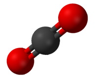
Carbon dioxide has two polar C-O bonds in a linear geometry.

Not every molecule with polar bonds is a polar molecule. Carbon dioxide (CO2) has two polar C=O bonds, but the geometry of CO2 is linear so that the two bond dipole moments cancel and there is no net molecular dipole moment; the molecule is nonpolar.
In methane, the bonds are arranged symmetrically (in a tetrahedral arrangement) so there is no overall dipole.

Examples of household nonpolar compounds include fats, oil, and petrol/gasoline. Therefore, most nonpolar molecules are water-insoluble (hydrophobic) at room temperature. Many nonpolar organic solvents, such as turpentine, are able to dissolve polar substances.

In the methane molecule (CH4) the four C−H bonds are arranged tetrahedrally around the carbon atom. Each bond has polarity (though not very strong). However, the bonds are arranged symmetrically so there is no overall dipole in the molecule. The diatomic oxygen molecule (O2) does not have polarity in the covalent bond because of equal electronegativity, hence there is no polarity in the molecule.

Amphiphilic molecules

Large molecules that have one end with polar groups attached and another end with nonpolar groups are described as amphiphiles or amphiphilic molecules. They are good surfactants and can aid in the formation of stable emulsions, or blends, of water and fats. Surfactants reduce the interfacial tension between oil and water by adsorbing at the liquid–liquid interface.

Predicting molecule polarity


Formula Description Example Name
Polar AB Linear molecules CO Carbon monoxide
HAx Molecules with a single H HF Hydrogen fluoride
AxOH Molecules with an OH at one end C2H5OH Ethanol
OxAy Molecules with an O at one end H2O Water
NxAy Molecules with an N at one end NH3 Ammonia
Nonpolar A2 Diatomic molecules of the same element O2 Dioxygen
CxAy Most carbon compounds CO2 Carbon dioxide

Determining the point group is a useful way to predict polarity of a molecule. In general, a molecule will not possess dipole moment, if the individual bond dipole moments of the molecule cancel each other out. This is because dipole moments are euclidean vector quantities with magnitude and direction, and a two equal vectors who oppose each other will cancel out.

Any molecule with a centre of inversion ("i") or a horizontal mirror plane ("σh") will not possess dipole moments. Likewise, a molecule with more than one Cn axis will not possess dipole moment because dipole moments cannot lie in more than one dimension. As a consequence of that constraint, all molecules with D symmetry (Schönflies notation) will, therefore, not have dipole moment because, by definition, D point groups have two or multiple Cn axis.

Since C1, Cs,C∞h Cn and Cnv point groups do not have a centre of inversion, horizontal mirror planes or multiple Cn axis, molecules in one of those point groups will have dipole moment.

Monday, July 17, 2017

Hydrogen bond

From Wikipedia, the free encyclopedia
 
AFM image of napthalenetetracarboxylic diimide molecules on silver-terminated silicon, interacting via hydrogen bonding, taken at 77  K.[1] ("Hydrogen bonds" in the top image are exaggerated by artifacts of the imaging technique.[2][3])
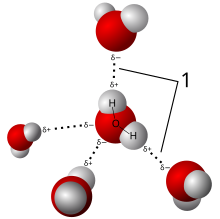
Model of hydrogen bonds (1) between molecules of water

A hydrogen bond is the electrostatic attraction between two polar groups that occurs when a hydrogen (H) atom covalently bound to a highly electronegative atom such as nitrogen (N), oxygen (O), or fluorine (F) experiences the electrostatic field of another highly electronegative atom nearby.
Hydrogen bonds can occur between molecules (intermolecular) or within different parts of a single molecule (intramolecular).[4] Depending on geometry and environment, the hydrogen bond free energy content is between 1 and 5 kcal/mol. This makes it stronger than a van der Waals interaction, but weaker than covalent or ionic bonds. This type of bond can occur in inorganic molecules such as water and in organic molecules like DNA and proteins.

Intermolecular hydrogen bonding is responsible for the high boiling point of water (100 °C) compared to the other group 16 hydrides that have much weaker hydrogen bonds.[5] Intramolecular hydrogen bonding is partly responsible for the secondary and tertiary structures of proteins and nucleic acids. It also plays an important role in the structure of polymers, both synthetic and natural.
In 2011, an IUPAC Task Group recommended a modern evidence-based definition of hydrogen bonding, which was published in the IUPAC journal Pure and Applied Chemistry. This definition specifies:
The hydrogen bond is an attractive interaction between a hydrogen atom from a molecule or a molecular fragment X–H in which X is more electronegative than H, and an atom or a group of atoms in the same or a different molecule, in which there is evidence of bond formation.[6]
An accompanying detailed technical report provides the rationale behind the new definition.[7]

Bonding

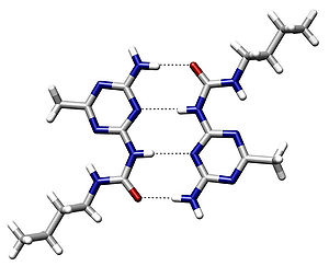
An example of intermolecular hydrogen bonding in a self-assembled dimer complex reported by Meijer and coworkers.[8] The hydrogen bonds are represented by dotted lines.
Intramolecular hydrogen bonding in acetylacetone helps stabilize the enol tautomer.

A hydrogen atom attached to a relatively electronegative atom will play the role of the hydrogen bond donor.[9] This electronegative atom is usually fluorine, oxygen, or nitrogen. A hydrogen attached to carbon can also participate in hydrogen bonding when the carbon atom is bound to electronegative atoms, as is the case in chloroform, CHCl3.[10][11][12] An example of a hydrogen bond donor is the hydrogen from the hydroxyl group of ethanol, which is bonded to an oxygen.

In a hydrogen bond, the electronegative atom not covalently attached to the hydrogen is named proton acceptor, whereas the one covalently bound to the hydrogen is named the proton donor.
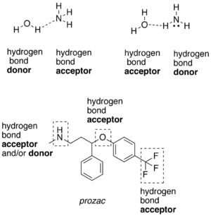
Examples of hydrogen bond donating (donors) and hydrogen bond accepting groups (acceptors)
Cyclic dimer of acetic acid; dashed green lines represent hydrogen bonds

In the donor molecule, the electronegative atom attracts the electron cloud from around the hydrogen nucleus of the donor, and, by decentralizing the cloud, leaves the atom with a positive partial charge. Because of the small size of hydrogen relative to other atoms and molecules, the resulting charge, though only partial, represents a large charge density. A hydrogen bond results when this strong positive charge density attracts a lone pair of electrons on another heteroatom, which then becomes the hydrogen-bond acceptor.

The hydrogen bond is often described as an electrostatic dipole-dipole interaction. However, it also has some features of covalent bonding: it is directional and strong, produces interatomic distances shorter than the sum of the van der Waals radii, and usually involves a limited number of interaction partners, which can be interpreted as a type of valence. These covalent features are more substantial when acceptors bind hydrogens from more electronegative donors.

The partially covalent nature of a hydrogen bond raises the following questions: "To which molecule or atom does the hydrogen nucleus belong?" and "Which should be labeled 'donor' and which 'acceptor'?" Usually, this is simple to determine on the basis of interatomic distances in the X−H···Y system, where the dots represent the hydrogen bond: the X−H distance is typically ≈110 pm, whereas the H···Y distance is ≈160 to 200 pm. Liquids that display hydrogen bonding (such as water) are called associated liquids.

Hydrogen bonds can vary in strength from very weak (1–2 kJ mol−1) to extremely strong (161.5 kJ mol−1 in the ion HF
2
).[13][14] Typical enthalpies in vapor include:
  • F−H···:F (161.5 kJ/mol or 38.6 kcal/mol)
  • O−H···:N (29 kJ/mol or 6.9 kcal/mol)
  • O−H···:O (21 kJ/mol or 5.0 kcal/mol)
  • N−H···:N (13 kJ/mol or 3.1 kcal/mol)
  • N−H···:O (8 kJ/mol or 1.9 kcal/mol)
  • HO−H···:OH+
    3
    (18 kJ/mol[15] or 4.3 kcal/mol; data obtained using molecular dynamics as detailed in the reference and should be compared to 7.9 kJ/mol for bulk water, obtained using the same molecular dynamics.)
Quantum chemical calculations of the relevant interresidue potential constants (compliance constants) revealed[how?] large differences between individual H bonds of the same type. For example, the central interresidue N−H···N hydrogen bond between guanine and cytosine is much stronger in comparison to the N−H···N bond between the adenine-thymine pair.[16]

The length of hydrogen bonds depends on bond strength, temperature, and pressure. The bond strength itself is dependent on temperature, pressure, bond angle, and environment (usually characterized by local dielectric constant). The typical length of a hydrogen bond in water is 197 pm. The ideal bond angle depends on the nature of the hydrogen bond donor. The following hydrogen bond angles between a hydrofluoric acid donor and various acceptors have been determined experimentally:[17]

Acceptor···donor VSEPR geometry Angle (°)
HCN···HF linear 180
H2CO···HF trigonal planar 120
H2O···HF pyramidal 46
H2S···HF pyramidal 89
SO2···HF trigonal 142

History

In the book The Nature of the Chemical Bond, Linus Pauling credits T. S. Moore and T. F. Winmill with the first mention of the hydrogen bond, in 1912.[18][19] Moore and Winmill used the hydrogen bond to account for the fact that trimethylammonium hydroxide is a weaker base than tetramethylammonium hydroxide. The description of hydrogen bonding in its better-known setting, water, came some years later, in 1920, from Latimer and Rodebush.[20] In that paper, Latimer and Rodebush cite work by a fellow scientist at their laboratory, Maurice Loyal Huggins, saying, "Mr. Huggins of this laboratory in some work as yet unpublished, has used the idea of a hydrogen kernel held between two atoms as a theory in regard to certain organic compounds."

Hydrogen bonds in water

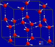
Crystal structure of hexagonal ice. Gray dashed lines indicate hydrogen bonds

The most ubiquitous and perhaps simplest example of a hydrogen bond is found between water molecules. In a discrete water molecule, there are two hydrogen atoms and one oxygen atom. Two molecules of water can form a hydrogen bond between them; the simplest case, when only two molecules are present, is called the water dimer and is often used as a model system. When more molecules are present, as is the case with liquid water, more bonds are possible because the oxygen of one water molecule has two lone pairs of electrons, each of which can form a hydrogen bond with a hydrogen on another water molecule. This can repeat such that every water molecule is H-bonded with up to four other molecules, as shown in the figure (two through its two lone pairs, and two through its two hydrogen atoms). Hydrogen bonding strongly affects the crystal structure of ice, helping to create an open hexagonal lattice. The density of ice is less than the density of water at the same temperature; thus, the solid phase of water floats on the liquid, unlike most other substances.

Liquid water's high boiling point is due to the high number of hydrogen bonds each molecule can form, relative to its low molecular mass. Owing to the difficulty of breaking these bonds, water has a very high boiling point, melting point, and viscosity compared to otherwise similar liquids not conjoined by hydrogen bonds. Water is unique because its oxygen atom has two lone pairs and two hydrogen atoms, meaning that the total number of bonds of a water molecule is up to four. For example, hydrogen fluoride—which has three lone pairs on the F atom but only one H atom—can form only two bonds; (ammonia has the opposite problem: three hydrogen atoms but only one lone pair).
H−F···H−F···H−F
The exact number of hydrogen bonds formed by a molecule of liquid water fluctuates with time and depends on the temperature.[21] From TIP4P liquid water simulations at 25 °C, it was estimated that each water molecule participates in an average of 3.59 hydrogen bonds. At 100 °C, this number decreases to 3.24 due to the increased molecular motion and decreased density, while at 0 °C, the average number of hydrogen bonds increases to 3.69.[21] A more recent study found a much smaller number of hydrogen bonds: 2.357 at 25 °C.[22] The differences may be due to the use of a different method for defining and counting the hydrogen bonds.

Where the bond strengths are more equivalent, one might instead find the atoms of two interacting water molecules partitioned into two polyatomic ions of opposite charge, specifically hydroxide (OH) and hydronium (H3O+). (Hydronium ions are also known as "hydroxonium" ions.)
H−O H3O+
Indeed, in pure water under conditions of standard temperature and pressure, this latter formulation is applicable only rarely; on average about one in every 5.5 × 10⁸ molecules gives up a proton to another water molecule, in accordance with the value of the dissociation constant for water under such conditions. It is a crucial part of the uniqueness of water.

Because water may form hydrogen bonds with solute proton donors and acceptors, it may competitively inhibit the formation of solute intermolecular or intramolecular hydrogen bonds. Consequently, hydrogen bonds between or within solute molecules dissolved in water are almost always unfavorable relative to hydrogen bonds between water and the donors and acceptors for hydrogen bonds on those solutes.[23] Hydrogen bonds between water molecules have an average lifetime of 10−11 seconds, or 10 picoseconds.[24]

Bifurcated and over-coordinated hydrogen bonds in water

A single hydrogen atom can participate in two hydrogen bonds, rather than one. This type of bonding is called "bifurcated" (split in two or "two-forked"). It can exist, for instance, in complex natural or synthetic organic molecules.[25] It has been suggested that a bifurcated hydrogen atom is an essential step in water reorientation.[26]

Acceptor-type hydrogen bonds (terminating on an oxygen's lone pairs) are more likely to form bifurcation (it is called overcoordinated oxygen, OCO) than are donor-type hydrogen bonds, beginning on the same oxygen's hydrogens.[27]

Hydrogen bonds in DNA and proteins

The structure of part of a DNA double helix
Hydrogen bonding between guanine and cytosine, one of two types of base pairs in DNA.

Hydrogen bonding also plays an important role in determining the three-dimensional structures adopted by proteins and nucleic bases. In these macromolecules, bonding between parts of the same macromolecule cause it to fold into a specific shape, which helps determine the molecule's physiological or biochemical role. For example, the double helical structure of DNA is due largely to hydrogen bonding between its base pairs (as well as pi stacking interactions), which link one complementary strand to the other and enable replication.

In the secondary structure of proteins, hydrogen bonds form between the backbone oxygens and amide hydrogens. When the spacing of the amino acid residues participating in a hydrogen bond occurs regularly between positions i and i + 4, an alpha helix is formed. When the spacing is less, between positions i and i + 3, then a 310 helix is formed. When two strands are joined by hydrogen bonds involving alternating residues on each participating strand, a beta sheet is formed. Hydrogen bonds also play a part in forming the tertiary structure of protein through interaction of R-groups. (See also protein folding).

The role of hydrogen bonds in protein folding has also been linked to osmolyte-induced protein stabilization. Protective osmolytes, such as trehalose and sorbitol, shift the protein folding equilibrium toward the folded state, in a concentration dependent manner. While the prevalent explanation for osmolyte action relies on excluded volume effects, that are entropic in nature, recent Circular dichroism (CD) experiments have shown osmolyte to act through an enthalpic effect.[28] The molecular mechanism for their role in protein stabilization is still not well established, though several mechanism have been proposed. Recently, computer molecular dynamics simulations suggested that osmolytes stabilize proteins by modifying the hydrogen bonds in the protein hydration layer.[29]

Several studies have shown that hydrogen bonds play an important role for the stability between subunits in multimeric proteins. For example, a study of sorbitol dehydrogenase displayed an important hydrogen bonding network which stabilizes the tetrameric quaternary structure within the mammalian sorbitol dehydrogenase protein family.[30]

A protein backbone hydrogen bond incompletely shielded from water attack is a dehydron. Dehydrons promote the removal of water through proteins or ligand binding. The exogenous dehydration enhances the electrostatic interaction between the amide and carbonyl groups by de-shielding their partial charges. Furthermore, the dehydration stabilizes the hydrogen bond by destabilizing the nonbonded state consisting of dehydrated isolated charges.[31]

Hydrogen bonds in polymers

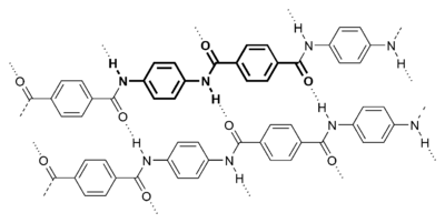
Para-aramid structure
A strand of cellulose (conformation Iα), showing the hydrogen bonds (dashed) within and between cellulose molecules.

Many polymers are strengthened by hydrogen bonds in their main chains. Among the synthetic polymers, the best known example is nylon, where hydrogen bonds occur in the repeat unit and play a major role in crystallization of the material. The bonds occur between carbonyl and amine groups in the amide repeat unit. They effectively link adjacent chains to create crystals, which help reinforce the material. The effect is greatest in aramid fibre, where hydrogen bonds stabilize the linear chains laterally. The chain axes are aligned along the fibre axis, making the fibres extremely stiff and strong. Hydrogen bonds are also important in the structure of cellulose and derived polymers in its many different forms in nature, such as wood and natural fibres such as cotton and flax.

The hydrogen bond networks make both natural and synthetic polymers sensitive to humidity levels in the atmosphere because water molecules can diffuse into the surface and disrupt the network. Some polymers are more sensitive than others. Thus nylons are more sensitive than aramids, and nylon 6 more sensitive than nylon-11.

Symmetric hydrogen bond

A symmetric hydrogen bond is a special type of hydrogen bond in which the proton is spaced exactly halfway between two identical atoms. The strength of the bond to each of those atoms is equal. It is an example of a three-center four-electron bond. This type of bond is much stronger than a "normal" hydrogen bond. The effective bond order is 0.5, so its strength is comparable to a covalent bond. It is seen in ice at high pressure, and also in the solid phase of many anhydrous acids such as hydrofluoric acid and formic acid at high pressure. It is also seen in the bifluoride ion [F−H−F].

Symmetric hydrogen bonds have been observed recently spectroscopically in formic acid at high pressure (>GPa). Each hydrogen atom forms a partial covalent bond with two atoms rather than one. Symmetric hydrogen bonds have been postulated in ice at high pressure (Ice X). Low-barrier hydrogen bonds form when the distance between two heteroatoms is very small.

Dihydrogen bond

The hydrogen bond can be compared with the closely related dihydrogen bond, which is also an intermolecular bonding interaction involving hydrogen atoms. These structures have been known for some time, and well characterized by crystallography;[32] however, an understanding of their relationship to the conventional hydrogen bond, ionic bond, and covalent bond remains unclear. Generally, the hydrogen bond is characterized by a proton acceptor that is a lone pair of electrons in nonmetallic atoms (most notably in the nitrogen, and chalcogen groups). In some cases, these proton acceptors may be pi-bonds or metal complexes. In the dihydrogen bond, however, a metal hydride serves as a proton acceptor, thus forming a hydrogen-hydrogen interaction. Neutron diffraction has shown that the molecular geometry of these complexes is similar to hydrogen bonds, in that the bond length is very adaptable to the metal complex/hydrogen donor system.[32]

Advanced theory of the hydrogen bond

In 1999, Isaacs et al.[33] showed from interpretations of the anisotropies in the Compton profile of ordinary ice that the hydrogen bond is partly covalent. However, this interpretation was challenged by Ghanty et al.,[34] who concluded that considering electrostatic forces alone could explain the experimental results. Some NMR data on hydrogen bonds in proteins also indicate covalent bonding.
Most generally, the hydrogen bond can be viewed as a metric-dependent electrostatic scalar field between two or more intermolecular bonds. This is slightly different from the intramolecular bound states of, for example, covalent or ionic bonds; however, hydrogen bonding is generally still a bound state phenomenon, since the interaction energy has a net negative sum. The initial theory of hydrogen bonding proposed by Linus Pauling suggested that the hydrogen bonds had a partial covalent nature. This remained a controversial conclusion until the late 1990s when NMR techniques were employed by F. Cordier et al. to transfer information between hydrogen-bonded nuclei, a feat that would only be possible if the hydrogen bond contained some covalent character.[35] While much experimental data has been recovered for hydrogen bonds in water, for example, that provide good resolution on the scale of intermolecular distances and molecular thermodynamics, the kinetic and dynamical properties of the hydrogen bond in dynamic systems remain unchanged.

Dynamics probed by spectroscopic means

The dynamics of hydrogen bond structures in water can be probed by the IR spectrum of OH stretching vibration.[36] In the hydrogen bonding network in protic organic ionic plastic crystals (POIPCs), which are a type of phase change material exhibiting solid-solid phase transitions prior to melting, variable-temperature infrared spectroscopy can reveal the temperature dependence of hydrogen bonds and the dynamics of both the anions and the cations.[37] The sudden weakening of hydrogen bonds during the solid-solid phase transition seems to be coupled with the onset of orientational or rotational disorder of the ions.[37]

Hydrogen bonding phenomena

  • Dramatically higher boiling points of NH3, H2O, and HF compared to the heavier analogues PH3, H2S, and HCl.
  • Increase in the melting point, boiling point, solubility, and viscosity of many compounds can be explained by the concept of hydrogen bonding.
  • Occurrence of proton tunneling during DNA replication is believed to be responsible for cell mutations.[38]
  • Viscosity of anhydrous phosphoric acid and of glycerol
  • Dimer formation in carboxylic acids and hexamer formation in hydrogen fluoride, which occur even in the gas phase, resulting in gross deviations from the ideal gas law.
  • Pentamer formation of water and alcohols in apolar solvents.
  • High water solubility of many compounds such as ammonia is explained by hydrogen bonding with water molecules.
  • Negative azeotropy of mixtures of HF and water
  • Deliquescence of NaOH is caused in part by reaction of OH with moisture to form hydrogen-bonded H
    3
    O
    2
    species. An analogous process happens between NaNH2 and NH3, and between NaF and HF.
  • The fact that ice is less dense than liquid water is due to a crystal structure stabilized by hydrogen bonds.
  • The presence of hydrogen bonds can cause an anomaly in the normal succession of states of matter for certain mixtures of chemical compounds as temperature increases or decreases. These compounds can be liquid until a certain temperature, then solid even as the temperature increases, and finally liquid again as the temperature rises over the "anomaly interval"[39]
  • Smart rubber utilizes hydrogen bonding as its sole means of bonding, so that it can "heal" when torn, because hydrogen bonding can occur on the fly between two surfaces of the same polymer.
  • Strength of nylon and cellulose fibres.
  • Wool, being a protein fibre, is held together by hydrogen bonds, causing wool to recoil when stretched. However, washing at high temperatures can permanently break the hydrogen bonds and a garment may permanently lose its shape.

Saturday, July 15, 2017

Carnot cycle

From Wikipedia, the free encyclopedia

The Carnot cycle is a theoretical thermodynamic cycle proposed by Carnot in 1824 and expanded upon by others in the 1830s and 1840s. It provides an upper limit on the efficiency that any classical thermodynamic engine can achieve during the conversion of heat into work, or conversely, the efficiency of a refrigeration system in creating a temperature difference (e.g. refrigeration) by the application of work to the system. It is not an actual thermodynamic cycle but is a theoretical construct.

Every single thermodynamic system exists in a particular state. When a system is taken through a series of different states and finally returned to its initial state, a thermodynamic cycle is said to have occurred. In the process of going through this cycle, the system may perform work on its surroundings, thereby acting as a heat engine. A system undergoing a Carnot cycle is called a Carnot heat engine, although such a "perfect" engine is only a theoretical construct and cannot be built in practice.[1] However, a microscopic Carnot heat engine has been designed and run.[2]

Essentially, there are two systems at temperatures Th and Tc (hot and cold respectively), which are so large that their temperatures are practically unaffected by a single cycle. As such, they are called "heat reservoirs". Since the cycle is reversible, there is no generation of entropy during the cycle; entropy is conserved. During the cycle, an arbitrary amount of entropy ΔS is extracted from the hot reservoir, and deposited in the cold reservoir. Since there is no volume change in either reservoir, they do no work, and during the cycle, an amount of energy ThΔS is extracted from the hot reservoir and a smaller amount of energy TcΔS is deposited in the cold reservoir. The difference in the two energies (Th-TcS is equal to the work done by the engine.

Stages

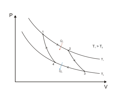
Figure 1: A Carnot cycle illustrated on a PV diagram to illustrate the work done.

The Carnot cycle when acting as a heat engine consists of the following steps:
  1. Reversible isothermal expansion of the gas at the "hot" temperature, T1 (isothermal heat addition or absorption). During this step (1 to 2 on Figure 1, A to B in Figure 2) the gas is allowed to expand and it does work on the surroundings. The temperature of the gas does not change during the process, and thus the expansion is isothermal. The gas expansion is propelled by absorption of heat energy Q1 from the high temperature reservoir and results in an increase of entropy of the gas in the amount {\displaystyle \Delta S_{1}=Q_{1}/T_{1}}.
  2. Isentropic (reversible adiabatic) expansion of the gas (isentropic work output). For this step (2 to 3 on Figure 1, B to C in Figure 2) the mechanisms of the engine are assumed to be thermally insulated, thus they neither gain nor lose heat (an adiabatic process). The gas continues to expand, doing work on the surroundings, and losing an amount of internal energy equal to the work that leaves the system. The gas expansion causes it to cool to the "cold" temperature, T2. The entropy remains unchanged.
  3. Reversible isothermal compression of the gas at the "cold" temperature, T2. (isothermal heat rejection) (3 to 4 on Figure 1, C to D on Figure 2) Now the surroundings do work on the gas, causing an amount of heat energy Q2 to leave the system to the low temperature reservoir and the entropy of the system decreases in the amount {\displaystyle \Delta S_{2}=Q_{2}/T_{2}}. (This is the same amount of entropy absorbed in step 1, as can be seen from the Clausius inequality.)
  4. Isentropic compression of the gas (isentropic work input). (4 to 1 on Figure 1, D to A on Figure 2) Once again the mechanisms of the engine are assumed to be thermally insulated, and frictionless, hence reversible. During this step, the surroundings do work on the gas, increasing its internal energy and compressing it, causing the temperature to rise to T1 due solely to the work added to the system, but the entropy remains unchanged. At this point the gas is in the same state as at the start of step 1.
In this case,
{\displaystyle \Delta S_{1}=\Delta S_{2}},
or,
{\displaystyle Q_{1}/T_{1}=Q_{2}/T_{2}}.
This is true as Q_{2} and T_{2} are both lower and in fact are in the same ratio as {\displaystyle Q_{1}/T_{1}}.

The pressure-volume graph

When the Carnot cycle is plotted on a pressure volume diagram, the isothermal stages follow the isotherm lines for the working fluid, adiabatic stages move between isotherms and the area bounded by the complete cycle path represents the total work that can be done during one cycle.

Properties and significance

The temperature-entropy diagram

Figure 2: A Carnot cycle acting as a heat engine, illustrated on a temperature-entropy diagram. The cycle takes place between a hot reservoir at temperature TH and a cold reservoir at temperature TC. The vertical axis is temperature, the horizontal axis is entropy.
A generalized thermodynamic cycle taking place between a hot reservoir at temperature TH and a cold reservoir at temperature TC. By the second law of thermodynamics, the cycle cannot extend outside the temperature band from TC to TH. The area in red QC is the amount of energy exchanged between the system and the cold reservoir. The area in white W is the amount of work energy exchanged by the system with its surroundings. The amount of heat exchanged with the hot reservoir is the sum of the two. If the system is behaving as an engine, the process moves clockwise around the loop, and moves counter-clockwise if it is behaving as a refrigerator. The efficiency to the cycle is the ratio of the white area (work) divided by the sum of the white and red areas (heat absorbed from the hot reservoir).

The behaviour of a Carnot engine or refrigerator is best understood by using a temperature-entropy diagram (TS diagram), in which the thermodynamic state is specified by a point on a graph with entropy (S) as the horizontal axis and temperature (T) as the vertical axis. For a simple closed system (control mass analysis), any point on the graph will represent a particular state of the system. A thermodynamic process will consist of a curve connecting an initial state (A) and a final state (B). The area under the curve will be:
Q=\int _{A}^{B}T\,dS\quad \quad (1)
which is the amount of thermal energy transferred in the process. If the process moves to greater entropy, the area under the curve will be the amount of heat absorbed by the system in that process. If the process moves towards lesser entropy, it will be the amount of heat removed. For any cyclic process, there will be an upper portion of the cycle and a lower portion. For a clockwise cycle, the area under the upper portion will be the thermal energy absorbed during the cycle, while the area under the lower portion will be the thermal energy removed during the cycle. The area inside the cycle will then be the difference between the two, but since the internal energy of the system must have returned to its initial value, this difference must be the amount of work done by the system over the cycle. Referring to figure 1, mathematically, for a reversible process we may write the amount of work done over a cyclic process as:
{\displaystyle W=\oint PdV=\oint (dQ-dU)=\oint (TdS-dU)=\oint TdS-\oint dU=\oint TdS\quad \quad \quad \quad (2)}
Since dU is an exact differential, its integral over any closed loop is zero and it follows that the area inside the loop on a T-S diagram is equal to the total work performed if the loop is traversed in a clockwise direction, and is equal to the total work done on the system as the loop is traversed in a counterclockwise direction.
A Carnot cycle taking place between a hot reservoir at temperature TH and a cold reservoir at temperature TC.

The Carnot cycle

A visualization of the Carnot cycle

Evaluation of the above integral is particularly simple for the Carnot cycle. The amount of energy transferred as work is
{\displaystyle W=\oint PdV=\oint TdS=(T_{H}-T_{C})(S_{B}-S_{A})}
The total amount of thermal energy transferred from the hot reservoir to the system will be
Q_{H}=T_{H}(S_{B}-S_{A})\,
and the total amount of thermal energy transferred from the system to the cold reservoir will be
Q_{C}=T_{C}(S_{B}-S_{A})\,
The efficiency \eta is defined to be:
\eta ={\frac {W}{Q_{H}}}=1-{\frac {T_{C}}{T_{H}}}\quad \quad \quad \quad \quad \quad \quad \quad \quad (3)
where
W is the work done by the system (energy exiting the system as work),
Q_{C} is the heat taken from the system (heat energy leaving the system),
Q_{H} is the heat put into the system (heat energy entering the system),
T_{C} is the absolute temperature of the cold reservoir, and
T_{H} is the absolute temperature of the hot reservoir.
S_{B} is the maximum system entropy
S_{A} is the minimum system entropy
This definition of efficiency makes sense for a heat engine, since it is the fraction of the heat energy extracted from the hot reservoir and converted to mechanical work. A Rankine cycle is usually the practical approximation.

The Reversed Carnot cycle

The Carnot heat-engine cycle described is a totally reversible cycle. That is, all the processes that comprise it can be reversed, in which case it becomes the Carnot refrigeration cycle. This time, the cycle remains exactly the same except that the directions of any heat and work interactions are reversed. Heat is absorbed from the low-temperature reservoir, heat is rejected to a high-temperature reservoir, and a work input is required to accomplish all this. The P-V diagram of the reversed Carnot cycle is the same as for the Carnot cycle except that the directions of the processes are reversed.[3]

Carnot's theorem

It can be seen from the above diagram, that for any cycle operating between temperatures T_{H} and T_{C}, none can exceed the efficiency of a Carnot cycle.

A real engine (left) compared to the Carnot cycle (right). The entropy of a real material changes with temperature. This change is indicated by the curve on a T-S diagram. For this figure, the curve indicates a vapor-liquid equilibrium (See Rankine cycle). Irreversible systems and losses of energy (for example, work due to friction and heat losses) prevent the ideal from taking place at every step.

Carnot's theorem is a formal statement of this fact: No engine operating between two heat reservoirs can be more efficient than a Carnot engine operating between those same reservoirs. Thus, Equation 3 gives the maximum efficiency possible for any engine using the corresponding temperatures. A corollary to Carnot's theorem states that: All reversible engines operating between the same heat reservoirs are equally efficient. Rearranging the right side of the equation gives what may be a more easily understood form of the equation. Namely that the theoretical maximum efficiency of a heat engine equals the difference in temperature between the hot and cold reservoir divided by the absolute temperature of the hot reservoir. Looking at this formula an interesting fact becomes apparent; Lowering the temperature of the cold reservoir will have more effect on the ceiling efficiency of a heat engine than raising the temperature of the hot reservoir by the same amount. In the real world, this may be difficult to achieve since the cold reservoir is often an existing ambient temperature.

In other words, maximum efficiency is achieved if and only if no new entropy is created in the cycle, which would be the case if e.g. friction leads to dissipation of work into heat. In that case the cycle is not reversible and the Clausius theorem becomes an inequality rather than an equality. Otherwise, since entropy is a state function, the required dumping of heat into the environment to dispose of excess entropy leads to a (minimal) reduction in efficiency. So Equation 3 gives the efficiency of any reversible heat engine.

In mesoscopic heat engines, work per cycle of operation fluctuates due to thermal noise. For the case when work and heat fluctuations are counted, there is exact equality that relates average of exponents of work performed by any heat engine and the heat transfer from the hotter heat bath.[4]

Efficiency of real heat engines

Carnot realized that in reality it is not possible to build a thermodynamically reversible engine, so real heat engines are even less efficient than indicated by Equation 3. In addition, real engines that operate along this cycle are rare. Nevertheless, Equation 3 is extremely useful for determining the maximum efficiency that could ever be expected for a given set of thermal reservoirs.

Although Carnot's cycle is an idealisation, the expression of Carnot efficiency is still useful. Consider the average temperatures,
\langle T_{H}\rangle ={\frac {1}{\Delta S}}\int _{Q_{in}}TdS
\langle T_{C}\rangle ={\frac {1}{\Delta S}}\int _{Q_{out}}TdS
at which heat is input and output, respectively. Replace TH and TC in Equation (3) by 〈TH〉 and 〈TC〉 respectively.

For the Carnot cycle, or its equivalent, the average value 〈TH〉 will equal the highest temperature available, namely TH, and 〈TC〉 the lowest, namely TC. For other less efficient cycles, 〈TH〉 will be lower than TH, and 〈TC〉 will be higher than TC. This can help illustrate, for example, why a reheater or a regenerator can improve the thermal efficiency of steam power plants—and why the thermal efficiency of combined-cycle power plants (which incorporate gas turbines operating at even higher temperatures) exceeds that of conventional steam plants. The first prototype of the diesel engine was based on the Carnot cycle.

Authorship of the Bible

From Wikipedia, the free encyclopedia ...